For the post spring break project we decided to focus on 3D drawing and CNC milling a small car. The following is an outline of the process so far:
Design
Given the available time, I chose to use an existing design. After searching through Pinterest I narrowed the focus to three nice looking wood car designs.
 |
| Car 1 |
 |
| Car 2 |
 |
| Car 3 |
3D Model in Fusion 360
We chose Fusion 360, over other CAD/CAM programs, because we can design, apply 3D tool paths and post a CNC program to any of our machines for free.
Before starting the 3D model I had to choose between the Sketch 3 modeling method or the Sculpt modeling method. I settled on the Sketch3 method for a few reasons. We used this method to model the totes earlier in the semester, so the students should grasp the concepts quickly. Additionally, I feel like the Sketch 3 method is more easily modified. Finally, I'm not at all good at using the sculpt tool and I didn't feel confident I could show the students anything of use.
Deciding the modeling method really pinpointed which car design to use. The Car 1 design is very sketch driven design friendly, while the Car 2 and Car 3 designs are much more Sculpt friendly.
 |
| Sketch 3: Use Car 1 photo to develop driving sketches in 3 planes |
 |
Extrude using driving sketches
|
 |
| Add wheels for a hint of class |
CNC hold down method
Holding the material to be cut on the CNC is usually the hardest part of the process. One of the biggest challenges with a 3D shape is that the part needs to be cut in multiple orientations, and needs to come off and on the machine with precision. So I brainstormed 3 different approaches, modeled them in Fusion 360 and settled on the
Dowl Method.
 |
| Tab Method: The square ends provide nice reference points, but the tabs may not provide enough support and need to be removed by hand |
 |
| Dissecting Method: By cutting up the model you can machine all parts in one operation and then combine after machining by hand |
 |
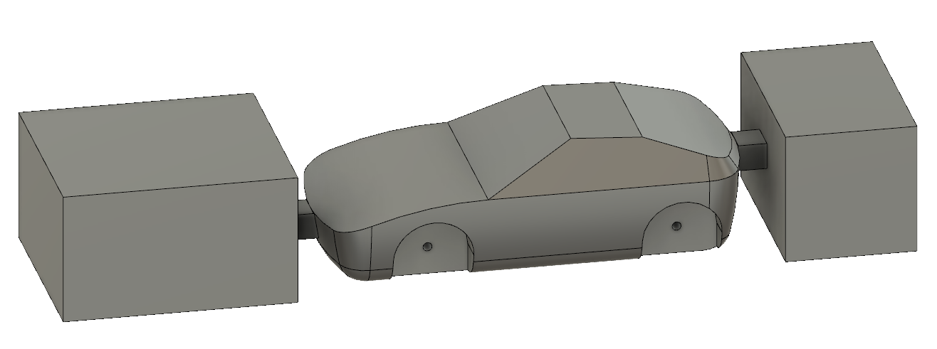
| Dowel Method: Using dowels to accurately locate and hold the part between operations |
Generate CNC Tool path
I chose to use a 1/4" ball round router bit for the CNC tool path. )The ball round profile usually yields the cleanest results for this type of operation.)
 |
| 1/4" Ball Round Router Bit |
I determine the cut sequence and apply paths in Fusion 360
 |
| Setup 1: Cut Bottom Profile |
 |
| Setup 2: Cut dowel Holes in setup board |
 |
| Setup 3: Cut top profile |
Cut sample on the CNC
Originally, we planned on using wood for the car, however a recent school project left us with an excessive amount of left over 1" thick pink foam. The foam is free and it is very forgiving on the first time CNC programmer.
 |
| 1. Cut Bottom Face |
 |
| 2. Cut Dowel holes into setup piece |
 |
| 3. Add magical double sided tape |
 |
| 4. Cut top side |
Now that the process is fairly worked, out Jaime will work on replicating the process on the X-carve CNC machine and I will move onto creating the class tutorial videos.
-Ryan


Thanks!!!
ReplyDelete